Speech Recognition in Scratch 3 - turning Hello into Bonjour!
The Raspberry Pi Foundation recently released a programming activity Alien Language , with support Dale from Machine Learning for Kids , tha...
PS3 Controller to move a USB Robot Arm
Guest Blogger Hiren Mistry, Nuffield Research Placement Student working at the University of Northampton. How to use a PS3 Controller to...
Scratch Robot Arm
It is not physical but CBiS Education have release a free robot arm simulator for Scratch. Downloadable from their site http://w...
Tinkercad and Microbit: To make a neuron
The free online CAD (and so much more) package Tinkercad https://www.tinkercad.com/ under circuits; now has microbits as part of the list ...
Escape the Maze with a VR robot - Vex VR
You don't need to buy a robot to get programming a robot, now there are a range of free and relatively simple to start with robot simula...
Easy, Free and no markers Augmented Reality - location based AR
For a few years, I have been a fan of Aframe and AR.js - these are fantastic tools for creating web-based Virtual and Augmented Reality. No...
Coral Dev Board and Raspberry Pi
This is the second of a planned occasional series of posts on playing with some of the current AI specific add-on processors for Intenet of ...
Explaining the Tinkercad microbit Neural network
In a previous post, I looked at developing a neural network in Tinkercad around the Microbit (details available here ) and the whole model ...
VR robot in a maze - from Blocks to Python
Recently I produced a post about playing with Vex Robotics VexCode VR blocks and the Maze Playground. The post finished with me saying I w...
4tronix Eggbit - cute and wearable - hug avoider
/ The ever-brilliant 4tronix have produced Eggbit https://shop.4tronix.co.uk/collections/microbit-accessories/products/eggbit; a cute, wear...
Showing posts with label neural network. Show all posts
Showing posts with label neural network. Show all posts
Friday 31 December 2021
Top 10 viewed posts 2021 on the Robot and Physical Computing Blog
Saturday 6 February 2021
Making a neural network in Tinkercad from Microbits
 |
| Tinkercad and microbit neural network |
In a previous post I produced a single neuron based around microbits in Tickercad - see here.
To extend this the basic ideas discussed in that the previous post where extended to three microbit joined together. In other words a network of neurones or neural network.
Basic requirements of a neuron are
Requirements
- By altering the bias (or w0 in the example), weights change the behaviour of switches changes.
-when switch is pressed a variable x1 or x2 is set to 1 depending on which button is pressed and when released it goes to 0.
- if (bias+w1*x1+w2*x2)>=0 then a T for True appears of the LEDs otherwise F for False is shown.
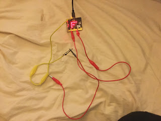
So by selecting the weights and connecting the outputs (p2) from the microbits labelled as Red and Green in the image above as inputs to the yellow microbit 'neuron' we can form a neural network. Switches as the inputs and the screen on the yellow 'neuron' as the output of the network showing true (T) or false(F).
So to build a XOR from the 'neurons'
'hidden layer'
Red microbit had the variables w0 set to -1 and W1 set to 0 and W2 set 1
Green microbit had the variables w0 set to -1 and W1 set to 1 and W2 set 0
'output layer'
Yellow microbit had the variables w0 set to -1 and W1 set to 1 and W2 set 1
All of this can be found at https://www.tinkercad.com/things/hPV4nU0Asr5-smooth-bojo or through the link shown below:
Tuesday 3 April 2018
How to produce a Microbit neural network
This is really part two of a set of post in response to a question from Carl Simmons (@Activ8Thinking) concerning building a micro:bit simple neuron. In the previous post a single neuron was produced. This post looks at producing a network of neurons, ie. neural network; looking to solve the problem that a single neuron can't solve, making an Exclusive OR gate (XOR)
1. Quick Overview
1.1 The neuron itself
The micro:bit objects used in Figure 1 were produced using the micro:bit Frtzing diagram available at https://github.com/microbit-foundation/dev-docs/issues/36 thanks to David Whale (@whalleygeek ) for these.
2. Neuron 1
This is the top left neurone in figure 1. This neurone is set to produce an output of TRUE (pin 2 going high) when the first input goes low and the second input goes high. The code for it is shown below.
3. Neuron 2
This is the bottom left neuron in figure 1. This neurone is set to produce an output of TRUE (pin 2 going high) when the first input goes high and the second input goes low. The code for it is shown below.
4. Output Neuron
Neuron 1
This is the right-hand neurone in figure 1. This neurone is set to produce an output of TRUE (pin 2 going high) when either inputs (outputs from neurons 1 and 2) goes high - in other words acting as an OR gate . The code for it is shown below.
The overall effect is when the two inputs to the network are high/TRUE then the output of the network (this neuron) is TRUE.
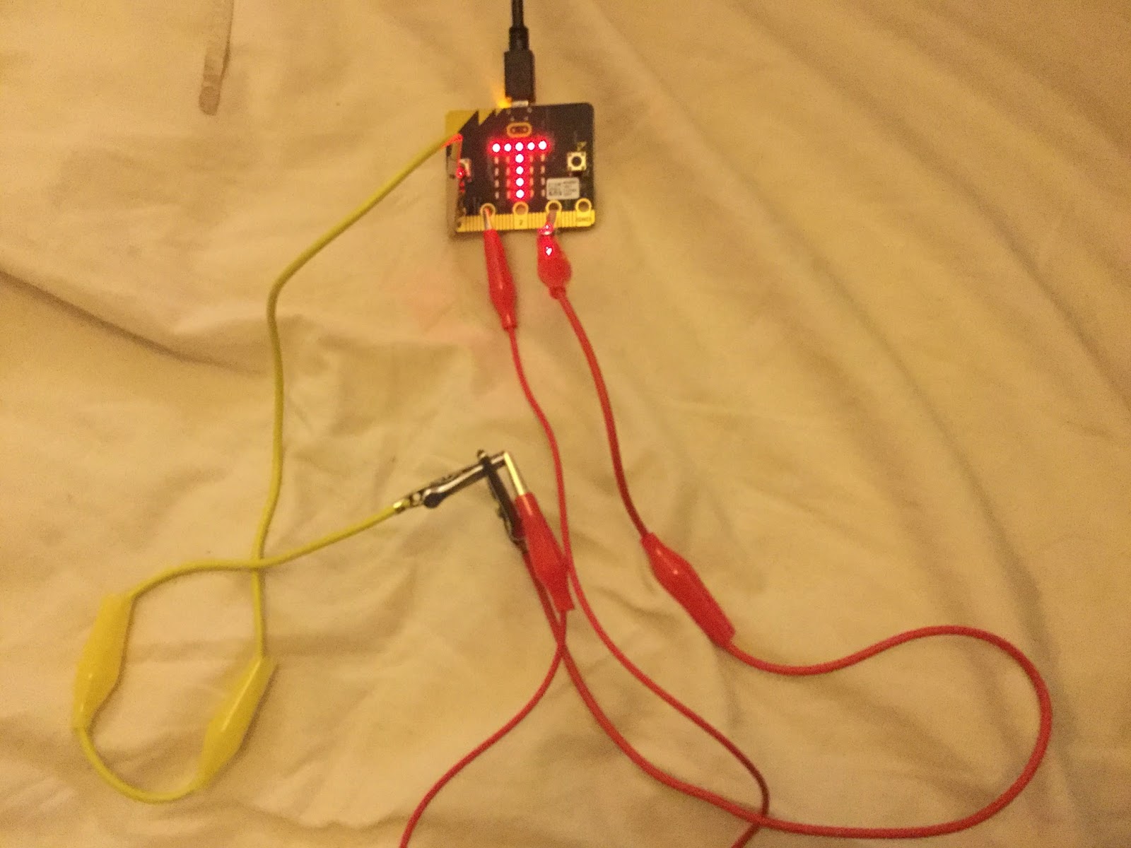
5. In Action
The wiring is messy but the effect is possible to see in these images. The top neuron is the output neuron.
6. Room for expansion
The neurons were 'trained' in this case by selecting the weights by hand, an improvement would be to get them to learn. How to do this on a micro:bit takes a bit more thinking about, but I would be interested in seeing how others solve that problem.
All opinions in this blog are the Author's and should not in any way be seen as reflecting the views of any organisation the Author has any association with. Twitter @scottturneruon
1. Quick Overview
1.1 The neuron itself
- Inputs are going to be binary
- Weighted sum is bias+W1*input1+w2*input2
- If weighted sum>=0 then the output is True (T on the LEDs) or '1'
- If weighted sum<0 then the output is False (F on the LEDs) or '0'
1.2 The XOR
Essentially for the two input case if the two inputs are different then the output is True.
The figure below shows the arrangement of the connections; pin 2 is the output of the neurons. The two micro:bits/neurons on the left of the picture taking in the two inputs, the same inputs go to these two neurons; the output from these neurons are the two inputs to the output neuron on the right.
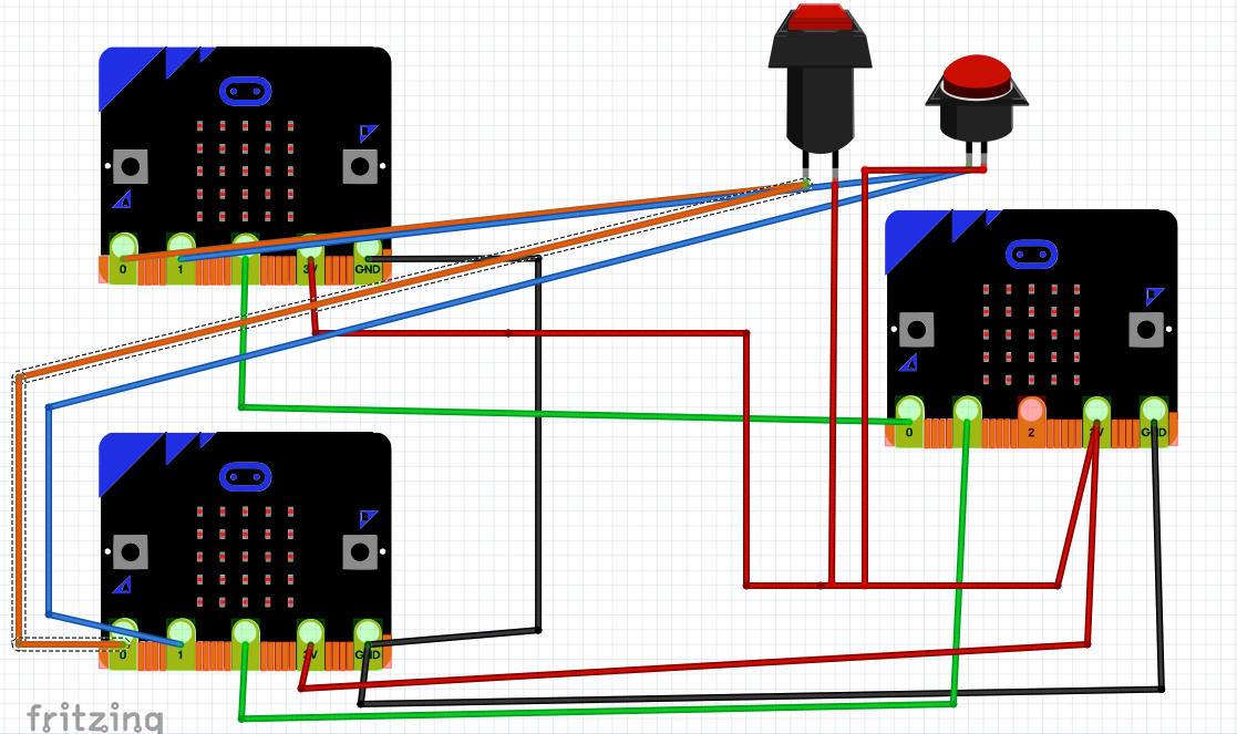 |
| figure 1 |
2. Neuron 1
This is the top left neurone in figure 1. This neurone is set to produce an output of TRUE (pin 2 going high) when the first input goes low and the second input goes high. The code for it is shown below.
3. Neuron 2
This is the bottom left neuron in figure 1. This neurone is set to produce an output of TRUE (pin 2 going high) when the first input goes high and the second input goes low. The code for it is shown below.
4. Output Neuron
Neuron 1
This is the right-hand neurone in figure 1. This neurone is set to produce an output of TRUE (pin 2 going high) when either inputs (outputs from neurons 1 and 2) goes high - in other words acting as an OR gate . The code for it is shown below.
The overall effect is when the two inputs to the network are high/TRUE then the output of the network (this neuron) is TRUE.
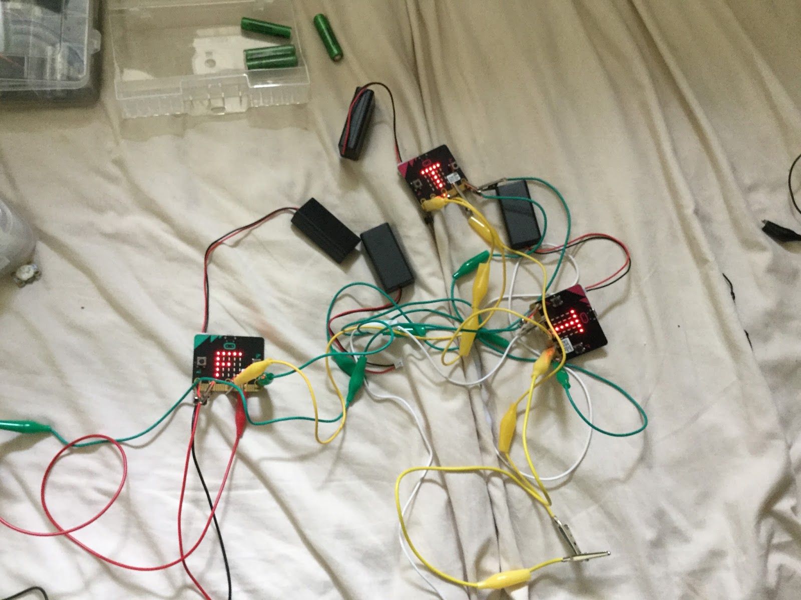
5. In Action
The wiring is messy but the effect is possible to see in these images. The top neuron is the output neuron.
 |
| figure 2: inputs to the network (input 1 low and input 2 high) |
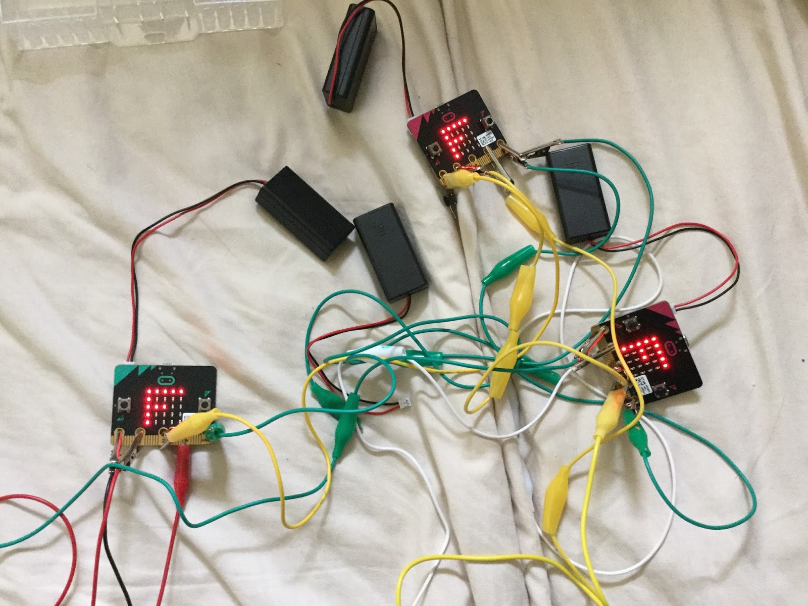
 |
| Figure 3: inputs to the network (input 1 high and input 2 low) |
 |
| figure 4: inputs to the network (both inputs the same) |
The neurons were 'trained' in this case by selecting the weights by hand, an improvement would be to get them to learn. How to do this on a micro:bit takes a bit more thinking about, but I would be interested in seeing how others solve that problem.
All opinions in this blog are the Author's and should not in any way be seen as reflecting the views of any organisation the Author has any association with. Twitter @scottturneruon
Friday 2 March 2018
Microbit Neuron - producing a single neuron using a microbit
This post is in response to a question from Carl Simmons (@Activ8Thinking) about has anyone built a microbit simple neuron.
Quick Overview
First attempt - A simple gate using the buttons A and B
So first attempt uses the A and B buttons on the Microbit as the two inputs and it produces T for true and F for false on the LEDs. So the weights produce an AND if the bias is changed from -2 to -1 you get an OR.
More Physical Solution for Single Neuron
So in this case the buttons are removed and P0 and P1 formed the inputs the weights are the same as in the previous example with the bias of -2 being used to produce a AND gate. Programming-wise this is a simpler solution than the previous one, no converting button presses into inputs.
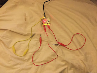
Figures below show the 'neuron' in action.
First, one shows the case when both inputs are '0' ie. not connected to 3v connection. The output is False (F on the LEDs)

Where next?
Adapting the code so it produces a digital output and then combining them into a small network to solve a problem that a single neuron can't do the Exclusive OR (XOR).
All opinions in this blog are the Author's and should not in any way be seen as reflecting the views of any organisation the Author has any association with. Twitter @scottturneruon
Quick Overview
- Inputs are going to be binary
- Weighted sum is bias+W1*input1+w2*input2
- If weighted sum>=0 then the output is True (T on the LEDs) or '1'
- If weighted sum<0 then the output is False (F on the LEDs) or '0'
First attempt - A simple gate using the buttons A and B
So first attempt uses the A and B buttons on the Microbit as the two inputs and it produces T for true and F for false on the LEDs. So the weights produce an AND if the bias is changed from -2 to -1 you get an OR.
More Physical Solution for Single Neuron
So in this case the buttons are removed and P0 and P1 formed the inputs the weights are the same as in the previous example with the bias of -2 being used to produce a AND gate. Programming-wise this is a simpler solution than the previous one, no converting button presses into inputs.
Figures below show the 'neuron' in action.
First, one shows the case when both inputs are '0' ie. not connected to 3v connection. The output is False (F on the LEDs)

This figure shows when only one input is '1', the output is False.

Finally what happens when both inputs are '1', the output goes to True (T on the LEDs).
Where next?
Adapting the code so it produces a digital output and then combining them into a small network to solve a problem that a single neuron can't do the Exclusive OR (XOR).
All opinions in this blog are the Author's and should not in any way be seen as reflecting the views of any organisation the Author has any association with. Twitter @scottturneruon
Monday 28 November 2016
Scratch for Neurones
1. Single Neurone
Instructions:
- Set the inputs by pressing the buttons marked input 1 and input 2 (Red is off(False or 0) and Green is on(True or 1))
- Change the weights by changing weights 1 to 3, wx goes with input x and weight 3 is the bias.
- To activate the neuron you need to click on the the yellow ball ('the neuron').
The video below show it in action and explains the code.
To see the code go to https://scratch.mit.edu/projects/131892234/ .
A slight modification click on the bell to change the weights
The code is available at https://scratch.mit.edu/projects/171190294/
2. Training a Neurone
In this part, the training of a neuron all written in Scratch is tackled. The video shows it action and you can have a go at using the software yourself at the end of the post. The Scratch code can be found at https://scratch.mit.edu/projects/132915502/
All opinions in this blog are the Author's and should not in any way be seen as reflecting the views of any organisation the Author has any association with. Twitter @scottturneruon
Monday 20 July 2015
Lego Robot and Neural Networks
An overview of using Lego RCX robots for teaching neural networks present at workshop in 2011.
The video below shows the robot trying out sets of weights for two neurones, until a set of weights are found that enable the robot to go around the circle.
All opinions in this blog are the Author's and should not in any way be seen as reflecting the views of any organisation the Author has any association with.
The video below shows the robot trying out sets of weights for two neurones, until a set of weights are found that enable the robot to go around the circle.
As a part of a set of tools I have found the following useful for teaching the principles of simple neurones.
Example code:
import josx.platform.rcx.*;
public class annlf{
public static void main(String[] args)
{
int w[][] ={//put weights here};
int o[]={1,1};
int s1,s2,res1,res2;
int sensor1=0,sensor2=0;
robot_1 tom=new robot_1();
Sensor.S1.activate();
Sensor.S3.activate();
for(;;){
sensor1=Sensor.S1.readValue();
sensor2=Sensor.S3.readValue();
LCD.showNumber(sensor1);
if (sensor1<42)
s1=1;
else
s1=0;
if (sensor2<42)
s2=1;
else
s2=0;
res1=w[0][1]*s1+w[0][2]*s2+w[0][0];
if (res1>=0)
o[0]=1;
else
o[0]=0;
res2=w[1][1]*s1+w[1][2]*s2+w[1][0];
if (res2>=0)
o[1]=1;
else
o[1]=0;
if ((o[0]==1)&&(o[1]==1))
tom.forward1(10);
if ((o[0]==0)&&(o[1]==0))
tom.backward1(20);
if ((o[0]==1)&&(o[1]==0))
tom.tlturn(20);
if ((o[0]==0)&&(o[1]==1))
tom.trturn(20);
LCD.refresh();
}
}
}
The
example code uses two neurones to produce a line follower. The nice thing about
this though is it easy to adapted this for a single neuron or multiple neuron
tasks. For more on this some examples can be found here.
The
above approaches used the Mindstorms RCX robots but it can equally be done with
the newer NXT robots.
All opinions in this blog are the Author's and should not in any way be seen as reflecting the views of any organisation the Author has any association with.
Subscribe to:
Posts (Atom)
Top posts on this blog in March 2024
The Top 10 viewed post on this blog in March 2024. Covering areas such as small robots, augmented reality, Scratch programming, robots. Micr...